GD&T is a system of symbols and rules that enable a designer/engineer to control geometric features of a part such as flatness, circularity, position, etc... The standard controlling the application of GD&T is ASME Y14.5 - 1994.
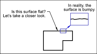
When a part is manufactured, there are always imperfections. It is impossible to manufacture anything that has perfect shape or form. For instance, a drawing shows a surface that is perfectly flat and horizontal, but in reality it is bumpy and not horizontal.
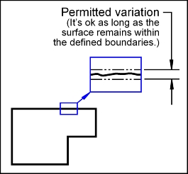
GD&T gives us the ability to say Yes, it is ok if a surface is bumpy, but lets limit the amount of bumpiness. GD&T provides the tools necessary to state the maximum allowable variation of a features form, orientation, profile, location, and runout from the perfect geometry implied on an engineering drawing.
The circle theory of GD&T promotes the idea of concurrent knowledge. GD&T is circular in nature. That is it is connected to design, manufacturing and inspection and back to design. When introducing GD&T, the focus will be on small circles covering all aspects of GD&T, but at limited depth. The circles will then increase in size to increase depth. CAUTION! Each circle will give the learner a complete picture, but does not give complete information.
The information contained in this website only covers "Circle 1" (the introductory circle)