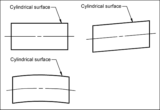
Consider the surfaces of the cylinders shown. Which cylindrical surfaces are straight? In reality, no cylindrical surface is perfectly straight. How would we know if the cylindrical surface on the bottom is straight enough?
The straightness tolerance may be used to control the straightness of a planar surface, a cylindrical surface, a center plane or a centerline. When controlling a cylindrical surface, the straightness control (u) defines how much each surface line element may deviate from a perfectly straight line.
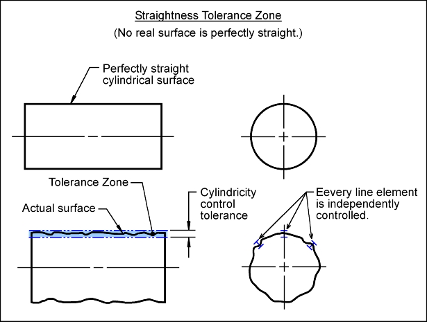
Straightness Control: Perfect straightness occurs when all points of an element lie on the same line. Straightness is a form control. The straightness control (u) defines how much each surface line element in a particular direction on a real part may vary from an ideal straight line.
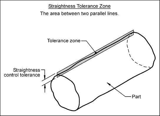
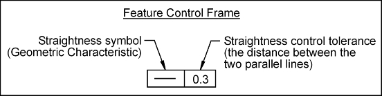
Tolerance Zone: The straightness tolerance zone is the area between two parallel lines. The distance between the parallel lines is the value of the straightness control tolerance. Each line element of the surface must, independently, lie within the area defined by the tolerance zone. The straightness tolerance does not control how cylindrical the part is.
Feature Control Frame: To control the straightness of a surface, a feature control frame (FCF) is used to apply the tolerance to the desired surface.
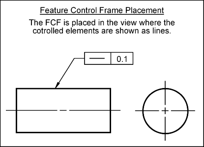
To apply a straightness control to a surface, the FCF is placed in the view where the controlled surface elements appear as lines. The FCF may point to the surface. The FCFs shown below apply a straightness tolerance to the entire surface. The surface elements must, independently, lie between two parallel lines that 0.1 mm apart.
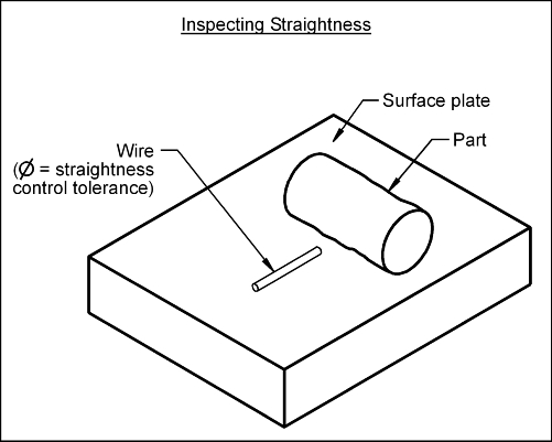
The straightness of a cylindrical surface may be inspected as follows: