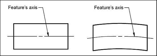
Consider the two axes shown. Which axis is straight? In reality, no features axis is perfectly straight. How would we know if the axis on the right is straight enough?
The straightness tolerance may be used to control the straightness of a planar surface, a cylindrical surface, a center plane or a centerline. When controlling an axis, the straightness control (u) defines how much the axis may deviate from a perfectly straight line. Straightness is the only form control that may be applied to either a surface or a FOS (Feature of Size). An axis is considered an FOS because it is attached to a feature that is defined by a size, in this case a diameter.
Straightness Control: Perfect straightness of and axis occurs when all points of the axis lie on a straight line. Straightness is a form control. The straightness control (u) defines how much an axis of a real part may vary from an ideal straight line.
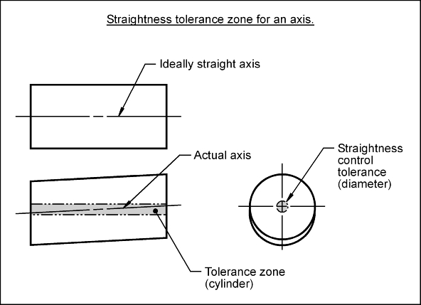
Tolerance Zone: The straightness tolerance zone for an axis is the volume defined by a cylinder. The axis being controlled must lie within the volume defined by the tolerance zone. The diameter of the cylinder is the value of the flatness control tolerance.
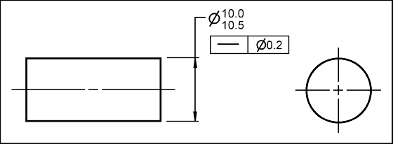
Feature Control Frame: To control the straightness of an axis, a feature control frame (FCF) is used to apply the tolerance to the desired axis. The straightness control tolerance value is preceded by a diameter symbol (n) to indicate that the value refers to the diameter of a cylinder.
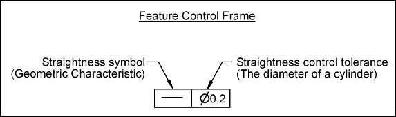
To apply the straightness control to an axis, the FCF is associated to the size dimension. Whenever a FCF is attached to a FOS dimension, it applies to the axis or centerplane of the feature. The FCF shown below applies a straightness tolerance to the parts axis. This axis must lie the volume of a cylinder that has a 0.2 mm diameter.
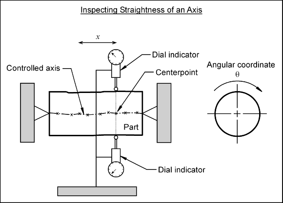
Before the straightness of an axis may be assessed, it has to be located. The location of the axis may be determined and inspected as follows: