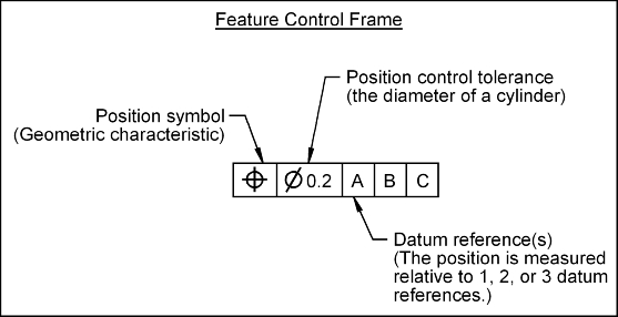
The position tolerance can control a center point, axis, or center plane. The position tolerance (j) defines how much the location of a feature may deviate from its true position.
Position Control: True position is the theoretically exact location of a feature of size (FOS). The true position is defined, on a drawing, through the use of basic dimension. Position is a location control. The position control (j) defines how much a center point, axis or center plane, on a real part, may vary from its true position.
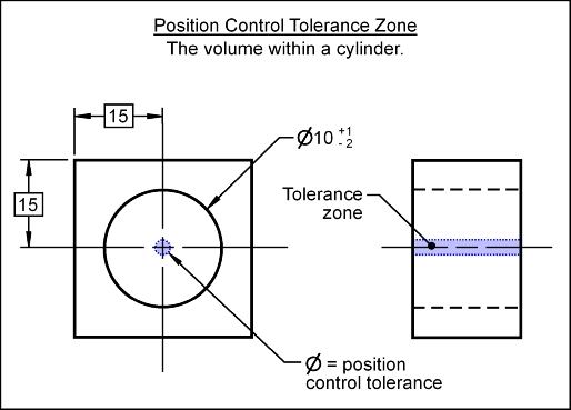
Tolerance Zone: The position tolerance zone for a controlled axis is the volume defined by a cylinder. The diameter of the cylinder is the stated value of the position control tolerance. The axis being controlled must lie with in the volume defined by the tolerance zone.
Feature Control Frame: To control the position of an axis, a feature control frame (FCF) is used to apply the tolerance to the FOS.
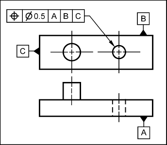
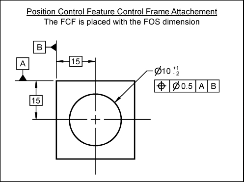
To apply the position control to an axis, the FCF is attached to the dimension of the FOS. In the following figure, the controlled axis must lie with in a cylinder whose diameter is 0.5 mm. The location of the center axis of the tolerance zone cylinder is defined by the basic dimensions locating the hole. The basic dimensions locate the ideal position of the hole relative to the datum feature A, B and C. The datum references are listed in order of importance.
The most common reason to use the position control is to ensure proper assembly of mating parts.
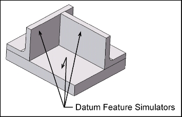
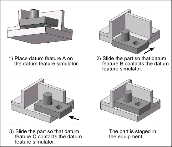
The position control may be inspected as follows: