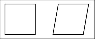
Consider the two parts shown. Which part has sides that are perfectly perpendicular to each other? In reality, no surface is perfectly perpendicular to another. How would we know if the part on the right has surfaces that are perpendicular enough?
The perpendicularity tolerance may be used to control the perpendicularity of a planar surface, a cylindrical surface, a center plane or a centerline. The perpendicularity control as applied to a surface or a center plane is very similar. Differences arise with the application of the feature control frame and inspection. When differences occur they will be explicitly explained.
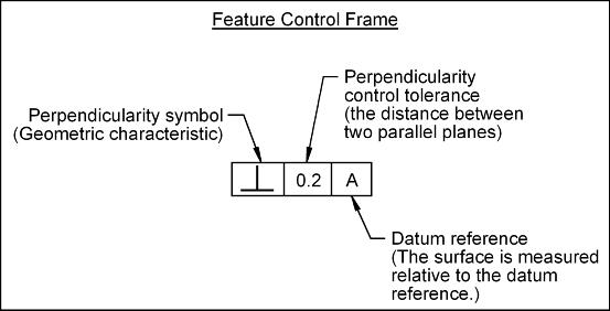
When controlling a surface, the perpendicularity control (b) defines how much a surface may deviate from a right angle (90o) with respect to an identified datum (a perfectly flat plane).
Perpendicularity Control: Perfect perpendcularity occurs when a surface is exactly at a right angle (90o) to a datum. Perpendicularity is an orientation control. The perpendicularity control (b) defines how much a surface on a real part may vary from being perpendicular to a specified datum.
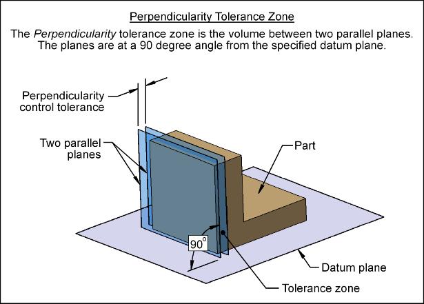
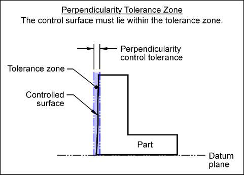
Tolerance Zone: The perpendicularity tolerance zone (when controlling a surface) is the volume between two parallel planes that are perpendicular to the datum plane. The distance between the parallel planes is the value of the perpendicularity control tolerance. The surface being controlled must lie within the volume defined by the tolerance zone.
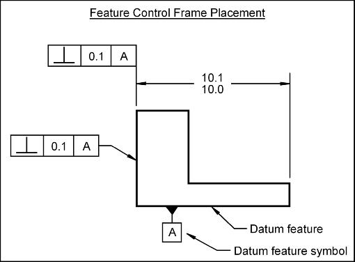
Feature Control Frame: To control the perpendicularity of a surface, a feature control frame (FCF) is used to apply the tolerance to the desired surface.
To apply a perpendicularity control to a surface, the FCF may point to the surface or be attached to the extension line that extends from the surface. The FCFs shown below apply a perpendicularity tolerance to the entire surface. The entire surface must lie between two parallel planes that are 0.1 mm apart. The planes are oriented 90o from datum A. The datum feature used to establish the datum is identified with a datum feature symbol.
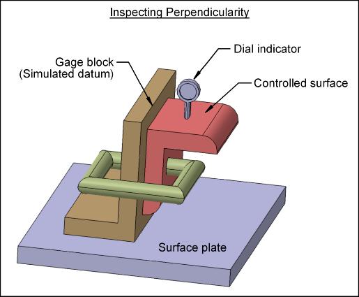
The perpendicularity control may be inspected as follows:
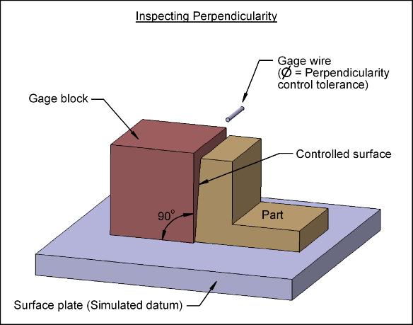
The perpendicularity control may also be inspected as follows: