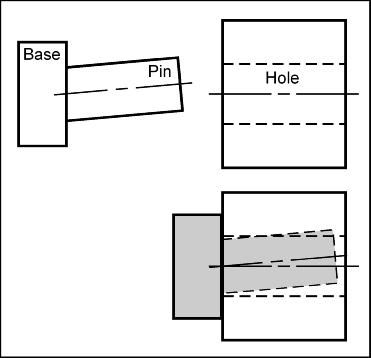
Consider the following pin-hole system. For the system to function properly, the pin needs to fit into the hole. Even thought the pin diameter is smaller than the hole diameter, the pin does not fit. What do we need to do in order to fix the problem? We need to straighten out the pin axis so that it is more perpendicular to the base.
The perpendicularity tolerance may be used to control the straightness of a planar surface, a cylindrical surface, a center plane or a centerline.
When controlling a surface, the perpendicularity control (b) defines how much an axis may deviate from a right angle (90o) with respect to an identified datum (a perfectly flat line or plane).
Perpendicularity Control: Perfect perpendcularity occurs when a surface is exactly at a right angle (90o) to a datum. Perpendicularity is an orientation control. The perpendicularity control (b) defines how much an axis on a real part may vary from being perpendicular to a specified datum.
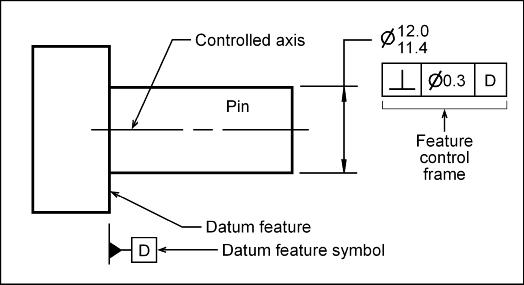
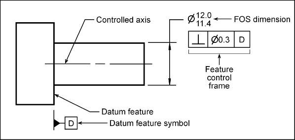
In the following figure, the pins axis is being controlled for perpendicularity. Ideally we want the axis to be at a right angle (90o) to datum feature D. Unfortunately, nothing can be manufactured to perfect perpendicularity. Therefore, a perpendicularity tolerance (b) is applied to the axis using a feature control frame (FCF). The perpendicularity control creates a tolerance zone in which the axis must reside.
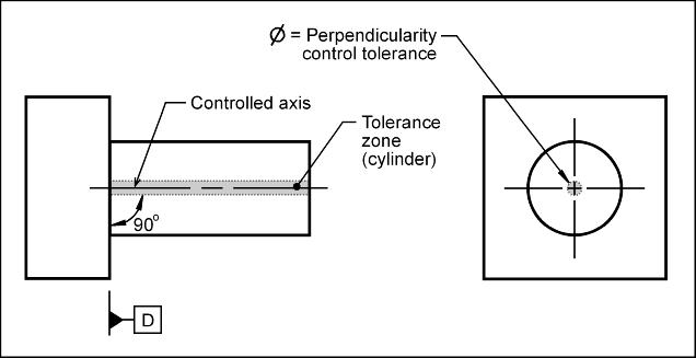
Tolerance Zone: The perpendicularity tolerance zone (when controlling an axis) is the volume within a cylinder that is perpendicular to the specified datum reference. The diameter of the cylinder is the perpendicularity control tolerance specified in the FCF. The axis being controlled must lie within the tolerance zone.
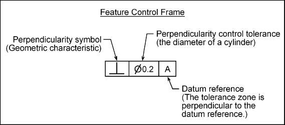
Feature Control Frame: To control the perpendicularity of a surface, a feature control frame (FCF) is used to apply the tolerance to the desired axis. The FCF contains the geometric characteristic symbol, the control tolerance value and between 1 and 3 datum references.
To apply a perpendicularity control to an axis, the FCF is placed with the axis feature of size (FOS) dimension.
The most common use of the axis perpendicularity control is to ensure proper assembly.
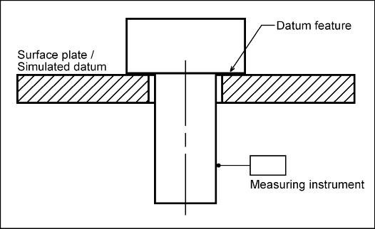
The perpendicularity control may be inspected as follows: