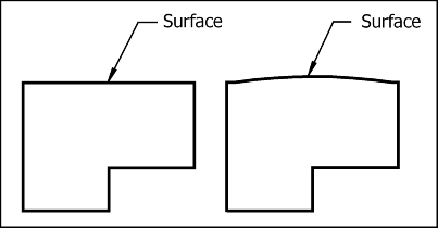
Consider the two surfaces shown. Which surface is perfectly flat? In reality, no surface is perfectly flat. How can we design a surface that is not perfectly flat, but flat enough to function properly? The flatness control tolerance.
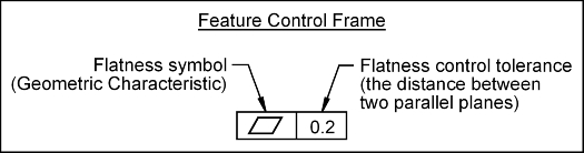
The flatness control (c) defines how much a parts surface may deviate from its perfect flat form.
Flatness Control: Perfect flatness is when all points of a surface lie in the same plane. Flatness is a form control. The flatness control (c) defines how much a surface on a real part may vary from the ideal flat plane.
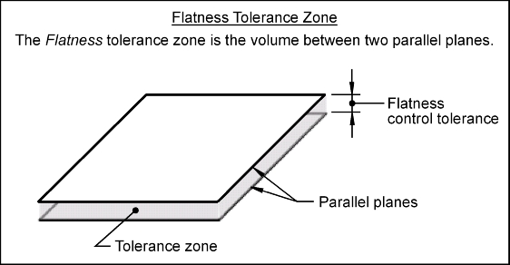
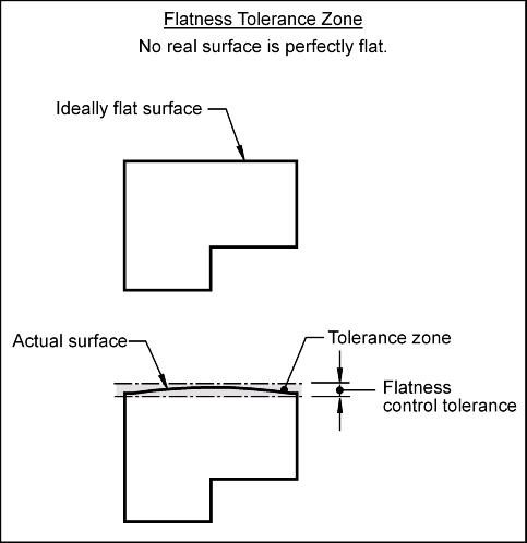
Tolerance Zone: The flatness tolerance zone is the volume between two parallel planes. The distance between the parallel planes is the stated flatness control tolerance value. The surface being controlled must lie within the volume defined by the tolerance zone.
Feature Control Frame: To control the flatness of a surface, a feature control frame (FCF) is used to apply the tolerance to the desired surface.
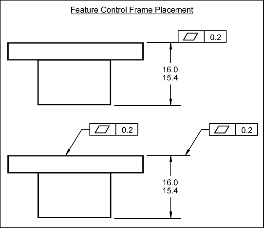
To apply a flatness control to a surface, the FCF may point to the surface, or can point to or rest on the extension line that extends from the surface. The FCF is placed in the view where the surface is viewed as a line. The FCF shown below applies a flatness tolerance to the entire surface. This surface must lie between two parallel planes that are spaced 0.2 mm apart.
The flatness control is used to ensure better contact between mating parts, or when a gasket or seal is to be used. It is also used to limit pitting and waviness of a surface.
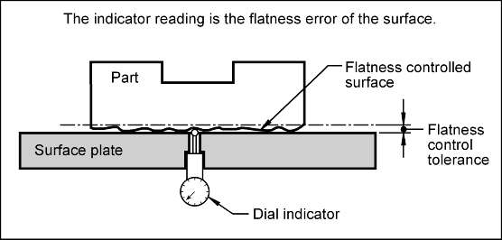
The flatness control may be inspected as follows: