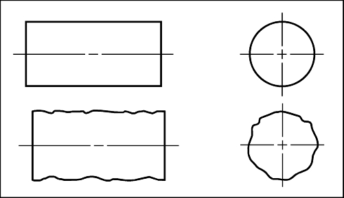
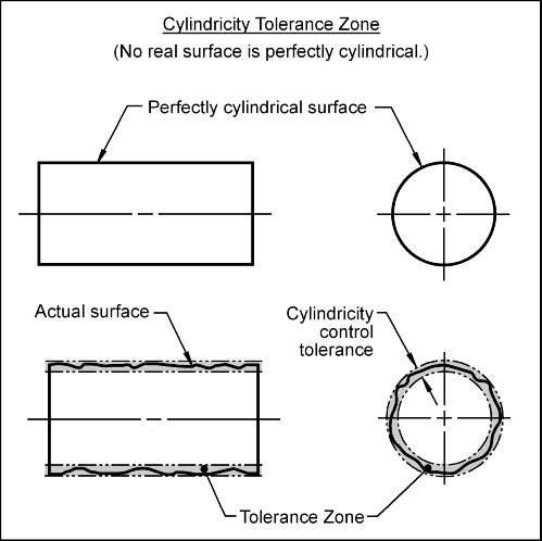
Consider the two cylinders shown. Which cylinder is perfectly circular? In reality, no cylindrical part is perfect. How would we know if the cylinder on the bottom is cylindrical enough?
The cylindricity control (g) defines how much a cylindrical surface of a part may deviate from a perfect cylinder.
Cylindricity Control: Perfect cylindricity is when all points of a surface of revolution are the same distance away from a common axis. Cylindricity is a form control. The cylindricity control (g) defines how much a cylindrical surface on a real part may vary from an ideal cylinder that is perfectly round, perfectly straight and has no taper.
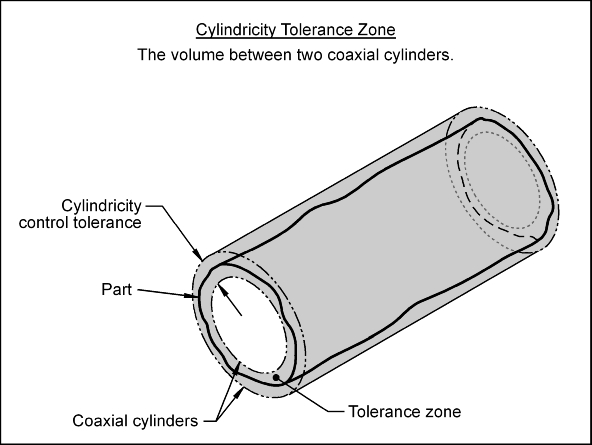
Tolerance Zone: The cylindricity tolerance zone is the volume between two coaxial cylinders. The radial distance between the two cylinders is the value of the cylindricity control tolerance. The surface being controlled must lie within the volume defined by the tolerance zone.
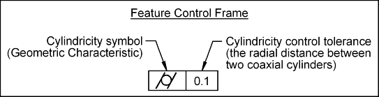
Feature Control Frame: To control the cylindricity of a surface, a feature control frame (FCF) is used to apply the tolerance to the desired surface.
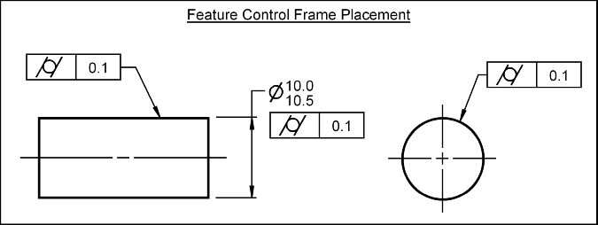
To apply the cylindricity control to a surface, the FCF may point to the surface in either the circular or rectangular view. The FCF shown below applies a cylindricity tolerance to the entire surface. This surface must lie between two coaxial cylinders whose radial separation is 0.1 mm.
The cylindricity control is used to limit out of roundness, taper and to ensure straightness of a shaft. If a shaft has too much cylindrical error, it could cause bushing or bearing failure. It can also protect against any large pits or bumps.
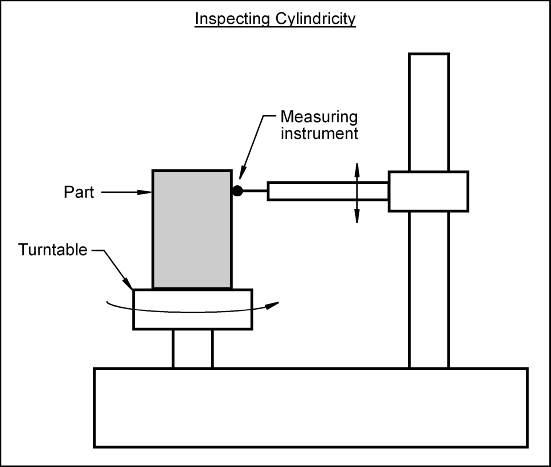
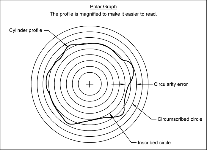
The cylindricity control may be inspected as follows: