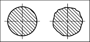
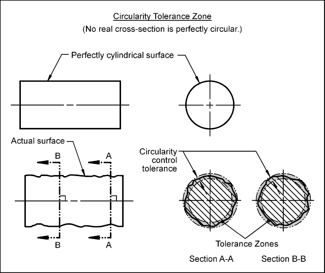
Consider the two cross-sections shown. Which cross-section is perfectly circular? In reality, no cross-section is perfectly circular. How would we know if the cross-section on the right is circular enough?
The circularity control (e) defines how much each circular cross-sections of a cylinder, sphere or cone may deviate from its perfect circular form.
Circularity Control: Perfect circularity is when all points of a surface of revolution at any cross-section are the same distance away from a common axis or center point. The surface of revolution may be a cylinder, sphere or cone. Circularity is a form control. The circularity control (e) defines how much the cross-sections of a surface of revolution on a real part may vary from an ideal circle.
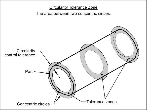
Tolerance Zone: The circularity tolerance zone is the area between two concentric circles that are perpendicular to the features axis or in the case of a sphere the circles share the same center point as the sphere. The radial distance between the two circles is the value of the circularity control tolerance. Each circular element of the surface being controlled must, independently, lie within the area defined by the tolerance zone.
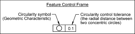
Feature Control Frame: To control the circularity of a surface, a feature control frame (FCF) is used to apply the tolerance to the desired surface.
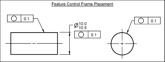
To apply the cylindricity control to a surface, the FCF may point to the surface in either the circular or rectangular view. The FCF shown below applies a circularity tolerance to the entire surface. Each cross-section of the surface must, independently, lie between two concentric circles whose radial separation is 0.1 mm.
The most common reason to use the circularity control is to limit out of roundness of a shaft diameter. Excessive circularity error may cause premature bearing or bushing failure.
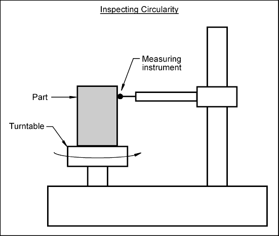
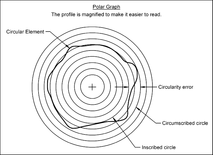
The circularity control may be inspected as follows: